Dake Euromatic Series User Manual
Browse online or download User Manual for Power saws Dake Euromatic Series. Dake Euromatic Series User Manual [de]
- Page / 36
- Table of contents
- BOOKMARKS
- INSTRUCTIONS 1
- SECTION I – Text 1
- If machine is to be operated 2
- Warning!!!!!! 11
- CAUTION!!!! 11
- Warning!!!!! 12
- WARNING!!!!! 13
- WARNING!!!! 17
- Caution!!!! 18
- EUROMATIC 370 PP 19
- VERTICAL HOLD DOWN VISE 19
- CAUTION!!! 22
- Warning!!!! 23
- TROUBLSHOOTING GUIDE 36
Summary of Contents
370 S 370 S L 370 PP 370 PP L 1 MODEL: _
370 S 370 S L 370 PP 370 PP L 10
370 S 370 S L 370 PP 370 PP L 11 Close the safety guard then turn on the power to the machine. Close the head feed control knob to the “0” setting.
370 S 370 S L 370 PP 370 PP L 12 Spindle speeds The larger or harder the material the slower the speed. The thinner or softer the material the fas
370 S 370 S L 370 PP 370 PP L 13 BLADE SELECTION FOR NON-FERROUS HEAD Proper Blade Selection 370 Non-Ferrous Same rules apply as with the ferrou
370 S 370 S L 370 PP 370 PP L 14 Different blade types There are many different grinds for carbide. Positive pitch and negative pitch. You may
370 S 370 S L 370 PP 370 PP L 15 SETTING THE HEAD PARAMETERS Warning!!!!! Never depress the limit switches with your finger. Your finger could
370 S 370 S L 370 PP 370 PP L 16 feed flow control valve to stop the head just above the material. Never have the blade adjusted closer than ½” to the
370 S 370 S L 370 PP 370 PP L 17 The air pressure can also be reduced by turning the main incoming air regulator down. Turning this down will also s
370 S 370 S L 370 PP 370 PP L 18 Loosen this handle and position it in an upwards position so it will not hit the casting while you rotate the head.
370 S 370 S L 370 PP 370 PP L 19 This adjustment is necessary when ever a different blade size is used on the machine. With a different blade size t
370 S 370 S L 370 PP 370 PP L 2 If machine is to be operated at 440 volt 3 phase power, please read the following warning. Call Dak
370 S 370 S L 370 PP 370 PP L 20 WARNING!!!!! DO NOT LET THE FEEDER VISE HIT THE VERTICAL HOLD DOWN DURING THE FEED CYCLE, THIS MAY CAUSE EXTENSIVE
370 S 370 S L 370 PP 370 PP L 21 SETTING THE BLADE PROTECTOR PARAMETERS 370PP CONTROL FUNCTIONS A. This scale shows the actual amps being drawn by
370 S 370 S L 370 PP 370 PP L 22 On occasion you may need to recalibrate your blade protection device. Common problems that may create the need for
370 S 370 S L 370 PP 370 PP L 23 Warning!!!! The feeder vise must be placed in the forward position (This switch is located on the far right hand sid
370 S 370 S L 370 PP 370 PP L 24 Figure 2 Figure 3 EXAMPLE: The thickness of the blade you are using is .098. The counter is zeroed out. This wi
370 S 370 S L 370 PP 370 PP L 25 PROGRAMMING FOR MULTIPLE INDEXING A: Three things that must be determined before programming for multiple index
370 S 370 S L 370 PP 370 PP L 26 G: On the piece counter, clear out the previous number that has been cut. Press the lower centered button to clear
370 S 370 S L 370 PP 370 PP L 27 B: Check gullets of the blade. Check teeth and surface of blade. If a chip is packed or welded in the gullets do no
370 S 370 S L 370 PP 370 PP L 28 These are only examples of different types of fixtures, Dake does not manufacture these.
370 S 370 S L 370 PP 370 PP L 29 HEAD CHANGE INSTRUCTIONS (Initial set-up and adjustments) If you have purchased the optional ferrous or non-ferrou
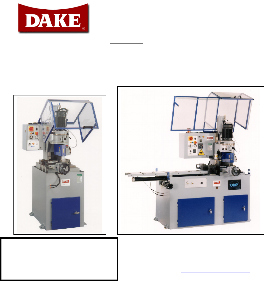
370 S 370 S L 370 PP 370 PP L 3 EUROMATIC 370 PP AUTOMATIC & SEMI-AUTOMATIC Specifications and Capacities TECHNICAL DATA 4-5 Unpacking and I
370 S 370 S L 370 PP 370 PP L 30 system for the non-ferrous head, using a ferrous cover plate. This plate will need to be modified, adding a discharge
370 S 370 S L 370 PP 370 PP L 31 certain amount of jerking without the cylinder connected, this is normal. If the head jerks excessively future adjust
370 S 370 S L 370 PP 370 PP L 32
370 S 370 S L 370 PP 370 PP L 33
370 S 370 S L 370 PP 370 PP L 34 EUROMATIC 370 PP / S MAINTENANCE SCHEDULE FERROUS HEAD 370PP /S A: Gear box. Maintain safe level of oil. Oil shou
370 S 370 S L 370 PP 370 PP L 35 Gear Box- 80 / 90 Gear Oil Way Oiler-Light Weight Way Oil Air Oiler - Tool Oil Clean DRO Strip-Clean Dry Rag E
370 S 370 S L 370 PP 370 PP L 36 Vise Gib Adjustment 370 PP / S check as needed Way Oiler 370 PP / S 2 pumps check / add DRO Magneti
370 S 370 S L 370 PP 370 PP L 4 Blade Specifications Unit Value Max. Blade Diameter Mm/inches 370mm/14.5 Inches Min. Blade Diameter Mm/inches 3
370 S 370 S L 370 PP 370 PP L 5 Technical Data Non-Ferrous head Blade Specifications Unit Value Max. Blade Diameter Mm/inches 370mm/14.5 Inches
370 S 370 S L 370 PP 370 PP L 6 UNPACKING AND INSTALLATION Unpacking A: Remove box or shrink wrap. Carefully inspect the machine for any physical d
370 S 370 S L 370 PP 370 PP L 7 16 amp service is recommended. Machines are rated at +/-10%. The wires are connected to the terminal block inside the
370 S 370 S L 370 PP 370 PP L 8 WARNING!!!!! Before performing the following operations, the electrical supply must be LOCKED OUT. NEVER ATTEMPT TO
370 S 370 S L 370 PP 370 PP L 9
Related products and manuals for Power saws Dake Euromatic Series
 (34 pages)
© 2020, manymanuals.com. All rights reserved. | 1.322 s |
 Manymanuals.com
 Manymanuals.de
 Manymanuals.fr
 Manymanuals.it
 Manymanuals.pl
 Manymanuals.cz
 Manymanuals.es
 Manymanuals-pt.com
Comments to this Manuals